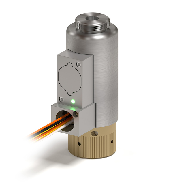
One product currently in development to meet these supervision needs is a special event recorder. This event recorder will capture an array of sensors and signals from functioning actuators per the customers’ requirements and then display them to the system owner. Depending upon the customers’ requirements, power for the event recorder can be supplied by either an internal battery or hardwired from the control panel. Current sensors and signals that the event recorder can collect include, but are not limited to, actuator installation supervision, actuator firing pin position, voltage monitoring, current monitoring, acceleration/shock load detection, temperature, and tank pressure and level.
Proper actuator installation and actuator firing pin position are valuable signals to know during and after the initial installation of the fire extinguishing system. The installation supervision signal confirms that the release actuator is properly installed onto the valve of the tank at the initial assembly and during periodic maintenance evaluations. This ensures that the system will not be disarmed due to a release actuator that was not properly installed. The actuator firing pin position informs the installer via LED light notifications whether the actuator firing pin is in the de-latched (fired) state or latched (armed) position.
Knowing the voltage, current, and acceleration signals gives the customer more information about why the fire suppression tank discharged. All three of these sensors are integrated directly into the event recorder’s circuit board. If the customer desires, the recorder can monitor any critical limits for voltage, current, and acceleration that would cause the actuator to fire and discharge the tank. Since each release actuator can be actuated electrically or manually with the use of the manual override button, these three recorded signals can reveal if the actuator was manually discharged or was commanded to actuate electrically.
In the event of an electrically discharged actuator, the recorder’s stored data will show both a voltage and current event. Milliseconds after the electrical signal is detected, the built-in accelerometer will capture a shock load in the axial direction, indicating the actuator has fired. The actuator firing pin position will also confirm that the unit has discharged. In the event the actuator is manually discharged, intentionally or accidentally, the recorder’s accelerometer will capture a shock load in the axial direction followed by a fired signal from the actuator firing pin. No voltage or current events will be captured during a manual event. The accelerometer is 3 axis, giving it the ability to capture impact loads in multiple planes. Non-axial impact loads to the actuator can also be captured, even though they do not necessarily discharge the actuator. This collected impact load data may indicate a need to review the actuator or tank for potential damage.
The recorder’s last captured signals provide external data in the areas of temperature, tank levels, and pressure. Specifically, thermocouples can supply data for ambient temperature and tank temperature. Thermocouples can be mounted to the event recorder’s circuit board, or they can be mounted remotely and hardwired. Tank pressure and level sensors can also be hardwired to the recorder for data collection. Once again, the customer can set limits for these signals to ensure the recorder indicates if a low tank level or pressure condition occurs.
The event recorder captures and stores each change in state of the actuator for future review. The log of these changes is stored internally on the local memory of the circuit board and can be reviewed via USB or Bluetooth. The log can also communicate with a compatible control panel via hardwire or wireless communication for more real-time data.
The recorder can identify four main actuator states. The first two states occur in operational mode and are known as “actuator ready” and “actuator fired.” In this operational mode, “actuator ready” status means that the release actuator is properly mounted to the valve (as indicated by the installation supervision and retracted firing pin signals) and is armed and ready. The state will change to “actuator fired” when the actuator’s firing pin status changes to the extended position. This state can be further studied alongside the voltage, current, and accelerometer signals to determine if the actuation was electrical or manual.
The second two states occur in maintenance mode and are again known as “actuator ready” or “actuator fired” status. Maintenance mode occurs when the actuator is removed from the valve/tank assembly. If maintenance is properly performed on the release actuator, the data log will show a change from “actuator ready” to “actuator fired” after the unit is electrically fired. Upon resetting the release actuator, the status will change back to “actuator ready.” Once the actuator is properly reinstalled onto the valve/tank assembly, the unit will return to operational mode “actuator ready.” This state monitoring feature is also a valuable tool for ensuring and confirming the required periodic maintenance of the release actuator.
The event recorder’s ability to capture all of these signals gives the system’s owner valuable insight into the status of the fire suppression system, allowing the owner to proactively address any issues. The recorder shows if the system is ready for use or not, and it alerts the system owner if the actuator is properly installed, mitigating the risk of system malfunction. In the event of an accidental discharge, the recorder shares important information about why the system discharged, showing any external or internal causes to hopefully prevent the accident from occurring again. Ultimately, this event recorder makes the entire fire suppression system safer, from installation to performance to maintenance, and gives the system’s owner more peace of mind.
