Maximizing Magnetics from B to H
Weight reduction equates to fuel economy gains, materials cost savings and design efficiencies. An optimized design maximizes performance while minimizing penalties, whether the goal is mass reduction, cost savings, performance improvement or energy consumption reduction. In reality, a design is optimized to meet a combination of these metrics. This is accomplished by manipulating multiple product-realization variables to tailor the product to meet market demands. In terms of solenoid actuators and valves (as well as most vehicle components), the key to optimizing mass, performance and overall efficiency is early involvement of expert component design resources.
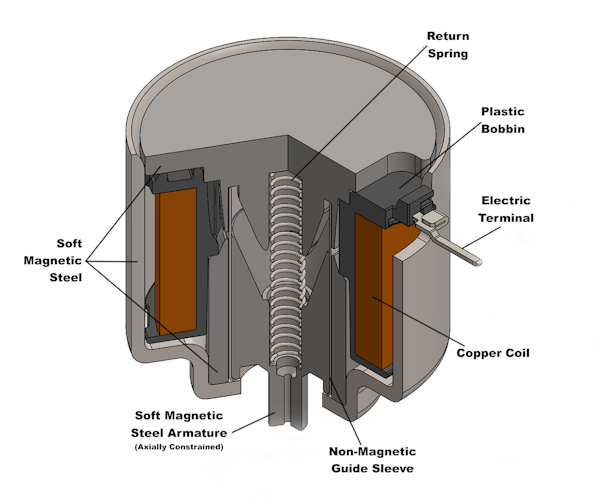
A solenoid, whether a valve or an actuator, has two necessary elements for proper operation. First, a current-carrying pathway is necessary to convert electrical energy to magnetic energy. Second, ferromagnetic materials are required to control and concentrate the magnetic energy. Typically, the ferromagnetic elements comprise soft plain carbon steel alloys, and the electrical conductors are copper wire coated with polymeric insulation appropriate for the environmental and electrical requirements of the device. (Figure 1 shows the typical layout of these components within a solenoid.)
Figure 1

When considering mass reduction, we often hear about advanced materials, structures or processing methods to gain strength leading to mass savings. However, these approaches typically carry a cost penalty. Solenoid actuators are no different. Advanced magnetic materials do exist, and there are suppliers who specialize in these materials, marketing them to magnetics designers. These enhanced alloys have unique material properties and behaviors, e.g. specific heat-treating requirements, machining/processing challenges, corrosion and wear resistance considerations. This means that beyond the cost of raw materials, there may be cost increases incurred in processing to end shape due to more machine time, tool wear and scrap rate.
In addition, post-machining heat treatment and/or surface conditioning can increase the overall cost. These materials are iron-based with alloying elements of cobalt, nickel, chromium, niobium, molybdenum, etc., and have costs that rise dramatically with performance. For automotive solenoid applications, the total mass of the device is typically in the range of 500 grams for a larger solenoid. A 30-percent reduction in mass may not warrant the price tag that comes with these advanced alloys, which can cost in excess of $250 USD/kg for the most capable materials at mass production volumes. It is, therefore, imperative when modeling with these alloys that the initial material cost, as well as processing costs, be accurately modeled to solve the cost/benefit equation.
Successful Designs Take Early Collaboration
What if design and cost constraints dictate that conventional materials must be used, but the market demands reduced mass while maintaining a competitive price point? Identifying realistic system needs and translating those requirements to component specifications in an accurate and cooperative fashion is the most important aspect to successful solenoid design. Successful design is achieved through early collaboration between engineering teams in the component design and system design disciplines. As an example, design elements that lead to risk of misalignment or off-axis forces can produce side-loading friction and significant wear penalties. Similarly, an interface design that leads to unfavorable tolerance stack ups can lead to increased costs or reduced quality.
For a solenoid, the single most important design requirement is stroke. The energy needed for actuation rises exponentially with increasing stroke. So, minimizing stroke requirements through creative system-design optimization is key to minimizing solenoid mass. The required level of synergy in the design of a component and system can only be achieved by tight collaboration between component and system design teams. Identification of all significant variables impacting desired performance metrics and systematic work to optimize the component and system design will result in significant savings in mass and cost, as well as a reduction in the cost of poor quality.
Different Factors Determine How to Reduce Coil Weight
When considering actual weight reduction in a solenoid, the first obvious element to consider is the solenoid’s coil. Solenoid coils make up a large portion of the solenoid’s overall mass in addition to being the most expensive component per unit mass in the solenoid (due to the use of copper wire). Without the coil, however, the solenoid would have no means of converting electrical energy into mechanical work. The role of the coil is to build up a magnetic field in a way that is usable to the ferromagnetic components. This is accomplished by utilizing the principle that electrical current flowing through a conductor will produce a magnetic field. The strength of this magnetic field depends greatly on two variables: the number of turns of conductive wire in the coil and the current driven through that wire. By using a smaller gauge wire, more turns can be fitted into a defined space. However, there is a drawback. Wire resistance per unit length is inversely proportional to the thickness of the wire. The coil will draw a much lower current for a given voltage. Thus, proper selection wire gauge and coil size is critical to the efficiency of the solenoid, as well as its overall weight, size, and cost.
Temperature is another factor that must be considered during solenoid coil design. As the temperature of the electrical conductor increases, so does its resistance. However, the rate at which the resistance rises with respect to temperature is dependent on the nominal resistance of the conductor. For example, a higher gauge (smaller cross section) wire’s resistance will increase more rapidly with respect to temperature than a lower gauge (larger cross section) wire of the same length. The importance of this characteristic can be seen when designing for corner conditions in a specification. Corner conditions exist when designing for a high ambient temperature with low voltage or a low ambient temperature with high voltage.
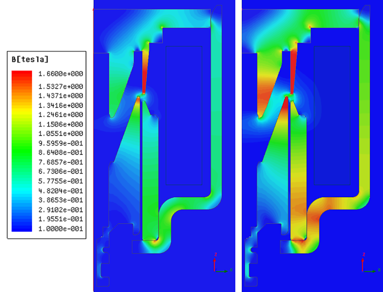
Typical engineering specifications for a solenoid will contain a maximum current draw, ambient temperature range, and supply voltage range. Thus, the solenoid coil must be designed so it does not exceed that current limit at the lowest ambient temperature (lowest resistance of the coil) and maximum supply voltage. The solenoid must still be able to operate at the highest operating temperature and lowest voltage. This is when the current draw of the coil will be at its lowest and therefore, produce the weakest magnetic field. In this instance, self-heating in the coil due to resistive losses must also be taken into account when calculating the maximum operating temperature of the coil. An example of the effect of temperature on the magnetic field strength can be seen in Figure 2. This shows the importance of early communication between design teams to determine what the realistic operating conditions of the solenoid are, preventing unrealistic expectations.
Figure 2

PWM Strategies
Challenges present themselves when an efficient and economical design cannot be produced for a given specification. For instance, in many automotive applications, ambient temperature ranges can be from -40°C to 150°C and the voltages ranges from 9V to 16V for a 12V system. In this case, the magnetic field produced by the coil can see a decrease as high as 70 percent between the two corner conditions. A solution often implemented in this scenario is pulse width modulation (PWM). Using a PWM control strategy allows current to be clipped to a lower value so it never reaches its maximum limit, while also reducing the self-heating of the coil. When used appropriately, PWM can allow for reductions in coil size as much as 40 percent, thus eliminating a substantial amount of copper and greatly reducing overall solenoid weight, size and cost.
A further factor in design cooperation affecting mass and cost is the working length (stroke) of a solenoid actuator. Recalling from earlier, the basic magnetic field strength of a coil is proportional to the number of turns of wire in the coil and the value of current flowing through that wire. The force achieved by a magnet is inversely proportional to the working distance and can be seen in Figure 3. Moreover, that relationship is exponential:

Reducing the working length required of the actuator has a very positive relationship with both the cost and capability of the final product. There are several implications of this fact as it pertains to solenoid design for an optimal mix of mass, cost and performance. Microns matter. In a magnetic circuit, there are small gaps between components that are referred to as “series gaps.” Additionally, there is the “working gap” of the solenoid, which is the space between the solenoid armature (moving component) and pole (stationary component), and is effectively equivalent to the stroke of the actuator.
Figure 3

Optimization at the component level typically means balancing the performance gains of smaller series gaps with the cost of tighter tolerances of parts. Tightening the radial tolerances between the moving armature and stationary components of a magnetic circuit can improve the force output of the solenoid. It can also have the undesired effect of increasing the radial forces exerted on the armature, leading to increased side loading and friction losses in the device. The balancing act is between the cost increase of part tolerances, the cost reduction of decreased copper due to more efficient magnetic circuits and the cost increase of friction mitigation strategy.
Avoiding Contamination
On the system level, environmental contamination can also require increased series gaps between the armature and the remainder of the circuit to maintain device function. Particulate contamination can lodge between moving parts of a solenoid and easily seize the mechanical system. Moreover, the solenoid is an electromagnet, so any magnetic particulates in the system will be attracted to the solenoid. This means that appropriate strategies for dealing with these particles must be introduced. Larger radial gaps in the plunger, adding debris mitigation grooves on the plunger, sealing the mechanical system against debris or filtering debris out of the fluid are all strategies with side effects on solenoid performance.
Considering filtering on the solenoid valve itself raises concerns of lifetime durability and valve function. A small filter on the valve can clog rather quickly in a heavily contaminated environment such as a new engine cooling system. This is particularly the case when fluid flow through the valve is only in one direction. In a hydraulic power and control environment, the fluid could flow in both directions through the valve, helping a filter to effectively self-clean or back flush.
Using larger gaps for debris tolerance or debris mitigation grooves has two effects on solenoid performance. One is the reduction of magnetic material capable of performing work. The second is an increase of friction within the device due to asymmetric radial loading on the magnetic circuit. If larger radial gaps are employed, there is room for the plunger to move off the center axis of the working magnetic circuit. Once this happens, the effect will be compounded by the eccentricity of the working plunger in this extra space causing the plunger to be pulled even harder towards one side of the working bore.
In the case of mitigation grooves, the same effect happens with a slight difference in the mechanism. When machining the debris mitigation grooves into a solenoid plunger, there will be asymmetrical features due to tolerance and machining capability. Again, this will cause an eccentricity of magnetically influenced material resulting in increased friction in the mechanical system. In both cases, increasing the size of the plunger and increasing the mass of copper used in the system are the primary recourse from a component level to overcome these introduced inefficiencies.
The final strategy for debris mitigation is to isolate or seal the mechanical system from debris. This is not always practical for an application, particularly in a fluid control valve. However, for an actuator, this may be an effective strategy. Providing an effective isolation approach also increases friction in the case of a dynamic shaft seal or resistive elastic forces due to a diaphragm-type seal. On a component level, the seal itself adds cost and mass and the increase in resistive forces calls for more magnetic material and more magnetic energy in the form of increasing copper mass.
Integrating Engineering Teams
With these considerations, it is important that engineering teams from the component and system level cooperatively integrate early in a project. With the goal of developing the most beneficial strategy for the system, open conversation near the outset of the project can help designers explore options such as upstream filtering in fluid control, cleanliness of manufactured system and components or other potential strategies for increasing system efficiency. All of these design considerations become critically important to optimizing the mass of the system and the cost.
Working environment considerations need to be addressed as an integrated project team for the optimization of cost and mass to produce an efficient end product. Particularly in the case of fluid control, whether it be coolant control, fuel metering, hydraulic control, etc., a fundamental openness and cooperation in regards to system function is critical to valve design. Particularly in the realm of solenoid valves, design teams on the component level usually include engineers that specialize in electromagnetics, mechanical systems, electronic control strategy and fluid mechanics. Conversely, a typical engineering specification for a valve (especially in new product development) is based on models, simulations and assumptions.
All models are to some degree incorrect, but if used with discipline and team cooperation, models become vitally useful. In a CFD-modeling (computational fluid dynamics) environment, it is necessary for a valve design team to understand what is happening both upstream and downstream of the valve, as well as to have a firm understanding of the physical principle of the end-use system. Typically, a valve modeled in CFD to a component specification will use a “test manifold” or the planned validation manifold for modeling the performance of the valve. This strategy may be valid as a finished product benchmarking exercise for quality control in manufacturing, but the details of the real system’s working characteristics are fundamental to the design of an efficient valve.
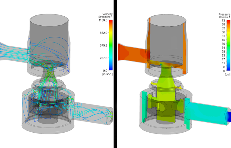
This cooperation can expose opportunities for further cost and mass savings by utilizing the specialized talents of component and system engineering teams. For example, a “sharp” corner 90° direction change in a molded rigid-elbow fitting will carry a much more severe pressure drop and head loss than a smooth bend of a molded polymer flexible hose. Figure 4 shows how CFD can be used to not just mathematically, but visually identify losses or restrictions in a system using pressure contours and streamlines. Identifying these losses in a cooperative environment can easily identify unforeseen system inefficiencies, mitigate these inefficiencies and end up with a more efficient design leading to benefits in system durability, mass reduction and cost savings. These are three terms that everyone loves to hear together.
Figure 4

Control Strategy Design
One additional benefit of team integration is in control strategy design. As mentioned earlier, a solenoid valve design team includes experts in electronic controls. The benefits to integrating this expertise into system design is two-fold. First, system friction can be reduced by as much as 40 percent by designing a PWM control signal to the right frequencies for system performance. This can lead to great reductions in size, mass and cost of an actuator. Second, in situations where precise fluid control is needed with a variable output pump, such as the coolant pump on a vehicle, the output will be directly related (in most cases) to the engine RPM. In this situation, it can be a big benefit to system efficiency and performance to utilize a solenoid valve design team to integrate simple and effective feedback controls.
Solenoids and solenoid valves are confined primarily to a world of iron alloys or steels and copper or other conductive materials. Due to the restrictions of physics, this means that they will be an inherently highly dense component. The absolute key to mass reduction in a solenoid actuator or valve, or more importantly the complete system that they are integrated into, is the early integration of engineering teams in the design stage. The optimal result of this integration is full utilization of the talents of two design teams (or more) to increase the knowledge base, specialization and core competencies of the end-product realization. Employing this cooperation can and will reduce development time, improve system function, reduce mass and optimize system cost to benefit.
This article was originally published by LightWeighting World Magazine in July 2017
Want to explore design examples?
TLX Technologies is the go-to custom solenoid partner of the world’s top brands, first-tier suppliers, and OEMs